
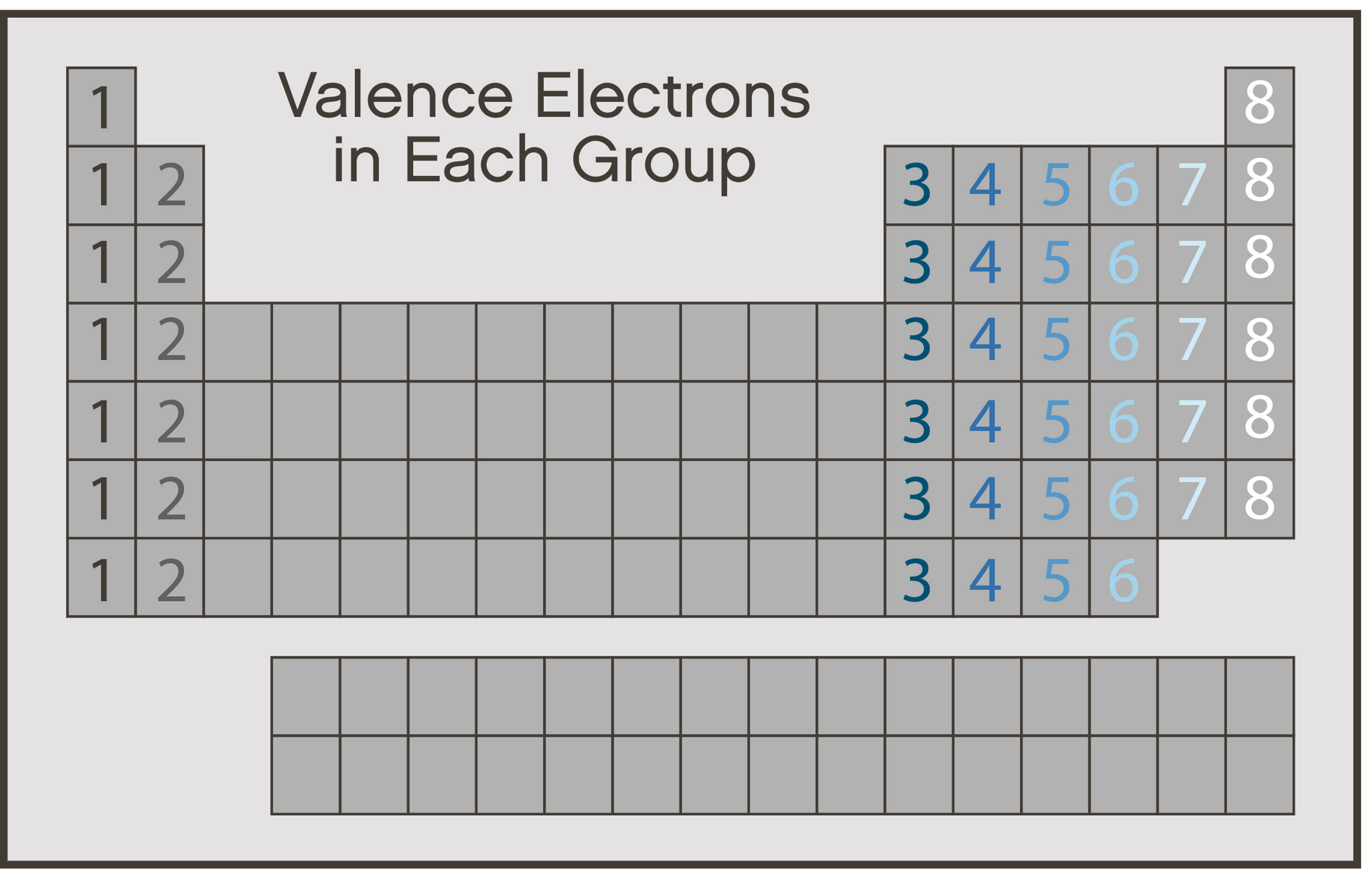
When two atoms approach each other and react with each other, it is their outer shells that come into contact first, and it is therefore the electrons in their outer shells that are normally involved in any chemical reaction. These electrons are known as valence electrons. So, it is the number of valence electrons in an atom's outer shell that determines, to a large extent, how that element will react chemically. The periodic table is arranged such that the main group elements (i.e., columns one through eight, not the transition elements) in the same column have the same number of valence electrons in their outer shell (Figure 1). For example, all of the elements in column one have one valence electron and all elements in column eight have eight valence electrons. However, helium is the exception to this formatting.
Between 1916 and 1919, Gilbert Newton Lewis, Walther Kossel, and Irving Langmuir came up with a theory to explain chemical bonding. This theory would be later called Lewis Theory and it is based on the following principles:
The octet rule states that elements gain or lose electrons to attain an electron configuration of the nearest noble gas. Atoms tend to form bonds in such a way as to satisfy the octet rule, with every atom surrounded by eight electrons. Noble gases have complete outer electron shells, which make them very stable. Other elements also seek stability, which governs their reactivity and bonding behavior. For example, elements in column seven (the halogens) are one electron away from filled energy levels, so they are very reactive. Fluorine, for example, has seven electrons in its outer electron shell. Fluorine readily bonds with other elements so that it can have a filled energy level, like neon.

Lewis dot diagrams for elements are a handy way of picturing valence electrons. The valence electrons are written as dots surrounding the symbol for the element: one dot is place on each side first, and when all four positions are filled, the remaining dots are paired with one of the first set of dots, with a maximum of two dots placed on each side. Lewis dot diagrams of the atoms in rows 1 and 2 of the periodic table are shown in Figure 2.
A Lewis symbol for an element is composed of a chemical symbol surrounded by dots that are used to represent valence electrons. An example of a Lewis symbol is shown below (Figure 3) with the element carbon, which has the electron configuration of 1s22s22p2:

This Lewis symbol shows that carbon has four valence electrons in its outer orbital and these four electrons play a major role in bonding of carbon molecules. Lewis symbols differ slightly for ions. When forming a Lewis symbol for an ion, the chemical symbol is surrounded by dots that are used to represent valence electrons, and the whole structure is placed in square brackets with a super-script representing the charge of the ion.
Electron dot diagrams (also known as Lewis dot structures) are commonly used to convey the structural formula of atomic and molecular bonds. In particular, they indicate the chemical bonding and lone electrons that exist within a compound. The first step in drawing an electron dot diagram is to determine how many shared bonds occur in the compound. This can be determined by referring to the Roman Numeral listed above the column of the atoms you are working with. For example, if you need to draw the structural formula for ammonia (NH3), you would find the Roman Numeral for five above the column with nitrogen (N), and the Roman Numeral for one above the column with hydrogen (H) in it. Thus (5) + (1 x 3) = 8 total electrons in ammonia. After you have determined how many electrons are in the compound, you need to position the atoms in a way that allows the compound to use that number of electrons. Referring back to NH3, you can start by placing a hydrogen molecule right next to the nitrogen, and inserting two electrons, represented by dots, in the center to indicate the covalent bond.
N : H
Continue to place the remaining hydrogen atoms and electron pairs around the nitrogen atom.
H
H N H
At this point, there are six of the eight dots (electrons) positioned. Hydrogen only has two electrons, and nitrogen needs eight electrons to be at steady state). Therefore, the remaining two electrons are placed next to the nitrogen atom without a hydrogen atom.

The diagram is now complete. Note that if you are working with a compound that has a positive or negative charge association, then the charge needs to be included in the total electron count.
The following steps describe how to construct Lewis structures for neutral molecules:

Molecular geometry is the three-dimensional manner in which the atoms of a molecule project into space (Figure 4). The shape of a molecule is important because it affects such physical properties as solubility, melting point, and boiling point. The shapes of molecules can be predicted from their Lewis structures by using a model developed about 30 years ago, known as the Valence Shell Electron Pair Repulsion (VSEPR) theory.
The VSEPR concept revolves around the idea that the electrons in a molecule repel each other and will try and get as far away from each other as possible. The electrons are "attached" to a central atom in the molecule and can "pivot" freely on the atom's surface to move away from the other electrons. Electrons come in several flavors:
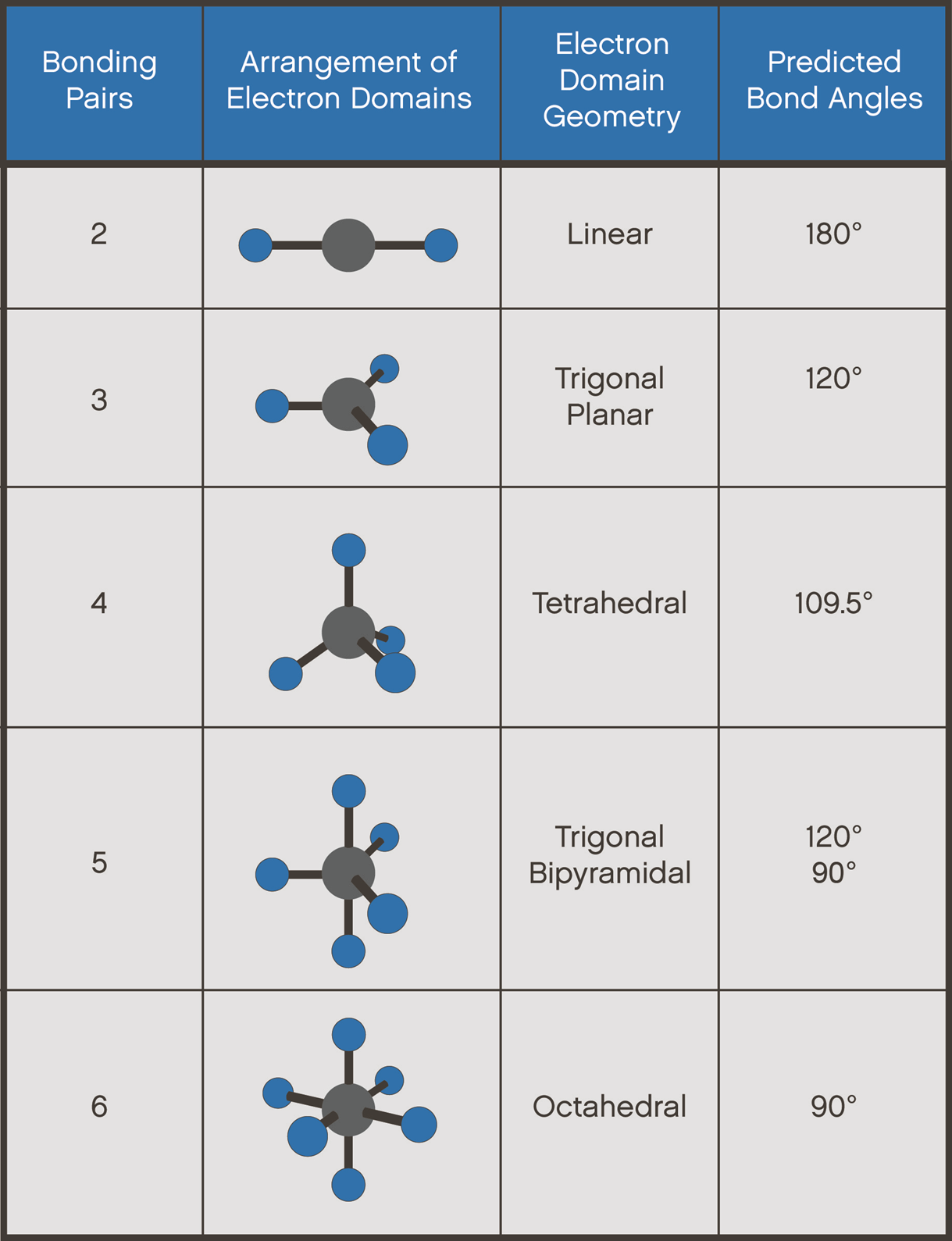
The VSEPR theory assumes that each atom in a molecule will achieve a geometry that minimizes the repulsion between electrons in the valence shell of that atom. The five compounds shown in Figure 4 can be used to demonstrate how the VSEPR theory can be applied to simple molecules.
Linear molecular geometry describes the arrangement of three or more atoms placed at an expected bond angle of 180°. For example, the central atom beryllium fluoride BeF2 where there are only two places in the valence shell where electrons can be found. Repulsion between these pairs of electrons can be minimized by arranging them so that they point in opposite directions. Thus, the VSEPR theory predicts that Be-F2 should be a linear molecule, with a 180° angle between the two Be-F bonds (Figure 4).
Trigonal planar is a molecular geometry model with one atom at the center and three atoms at the corners of a triangle, called peripheral atoms, all in one plane. There are three places on the central atom in boron trifluoride (BF3) where valence electrons can be found. Repulsion between these electrons can be mini-mized by arranging them toward the corners of an equilateral triangle. The VSEPR theory therefore predicts a trigonal planar geometry for the BF3 molecule, with a F-B-F bond angle of 120° (Figure 4).
In a tetrahedral molecular geometry, a central atom is located at the center with four substituents that are located at the corners of a tetrahedron. The bond angles are 109.5° when all four substituents are the same. For example, BeF2 and BF3 are both two-dimensional molecules in which the atoms lie in the same plane. If we place the same restriction on methane (CH4), we would get a square-planar geometry in which the H-C-H bond angle is 90°. If we let this system expand into three dimensions, however, we end up with a tetrahedral molecule in which the H-C-H bond angle is 109°28' (Figure 4).
A trigonal bipyramid formation is a molecular geometry with one atom at the center and five more atoms at the corners of a triangular dipyramid. For example, repulsion between the five pairs of valence electrons on the phosphorus atom in phosphorus pentafluoride (PF5) can be minimized by distributing these electrons toward the corners of a trigonal bipyramid. Three of the positions in a trigonal bipyramid are labeled equatorial because they lie along the equator of the molecule. The other two are axial because they lie along an axis perpendicular to the equatorial plane. The angle between the three equatorial positions is 120°, while the angle between an axial and an equatorial position is 90° (Figure 4).
An octahedral molecular geometry describes the shape of compounds wherein six atoms are symmetrically arranged around a central atom For example, there are six places on the central atom in sulfur hexafluoride (SF6) where valence electrons can be found. The repulsion between these electrons can be minimized by distributing them toward the corners of an octahedron. The term octahedron literally means "eight sides," but it is the six corners, or vertices, that interest us. To imagine the geometry of an SF6 molecule, locate fluorine atoms on opposite sides of the sulfur atom along the X, Y, and Z axes of an XYZ coordinate system (Figure 4).
Wedge and Dash Projection (Figure 5) is a means of representing a molecule in which three types of lines are used in order to represent the three-dimensional structure: (1) solid lines to represent bonds which are in the plane of the paper, (2) dashed lines to represent bonds that extend away from the viewer, and (3) wedge-shaped lines to represent bonds oriented facing the viewer.

Please click here to download the Pre-Lab Questions
Please click here to view the Experiment 1: Molecular Models of Neutral Molecules
Please click here to download the Experiment 1: Molecular Models of Neutral Molecules
Please click here to download the Post Lab questions.